

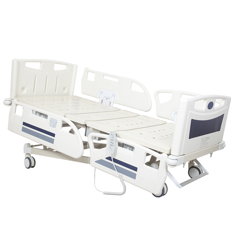
A buyer looks underneath an electric hospital bed. Several components are visible. There are electric actuators. There is a handset. There are cables. There may be a power supply or power connection. And somewhere under the bed there is usually another important electrical component: The control box. For many buyers, this component receives much less attention than the motors. Specifications may simply say: Four motors. Five functions. Hand control. Backup battery. But the electrical system is not simply a collection of independent motors connected directly to several buttons. The control box plays a central role in coordinating the electrical components of many electric hospital beds. A simplified system can be understood as: Power Input → Power Supply → Control Box → User Command → Actuator Output → Bed Movement. Understanding this architecture helps buyers ask better questions when comparing electric hospital bed configurations. The control box provides connection and control functions between the bed's electrical components according to the system design. The command may originate from a handset or another compatible control interface depending on the bed configuration. The control system determines which actuator is commanded to move according to the selected function. For example: Raise the backrest. Lower the backrest. Raise the leg section. Raise the bed height. The control system routes or processes the command according to its design. The actuator converts electrical input into linear movement that drives part of the bed structure. An electric linear actuator extends or retracts to move a bed section or mechanism. Its role belongs to the electrical control architecture. They may be mounted underneath the bed and connected by cables. The actuator moves. The control box controls or coordinates electrical connections and commands according to the system design. The user presses buttons to request movement. It processes or routes those commands within the compatible system. It does not provide the mechanical lifting force. The control architecture connects the requested function with the relevant actuator. Electrical architectures vary between manufacturers and component systems. Power conversion and control functions may be arranged differently depending on the system. Port arrangement, compatible actuators and control interfaces can vary. A basic electric bed and a more complex ICU-style bed may not use the same control architecture. The command begins at the handset or another compatible control interface. The electrical system interprets or routes the request according to its design. The selected actuator extends or retracts. The actuator drives the corresponding mechanical structure. The stopping behavior depends on the system design and the movement condition. That topic focuses on end-of-travel behavior. The focus is system structure. Control boxes are designed for particular electrical systems and configurations. An unused connection does not automatically mean the bed is missing a function. A bed can perform several movements through a coordinated electrical system. This has already been discussed separately in our actuator-system content. The system may provide connections for the actuators required by the bed configuration. The compatible handset may connect to the control system. Depending on the bed design, other compatible control components may also be integrated. The exact relationship depends on the electrical architecture. The control box must support the required compatible components. A control box should be evaluated by whether it suits the intended configuration. The exact connector and electrical configuration depend on the component system. Do not assume any actuator can be connected to any available port. This can support assembly and service work. A technician can identify which connection is being discussed more clearly. Cable routing, connector fit, strain relief and wiring inspection have already been covered separately. Today the ports matter because they show how the control box organizes the electrical system. It should be compatible with the actuators, control interface and other relevant electrical components. A visually similar control box should not automatically be considered interchangeable. Different brands can use different electrical architectures, connectors, control logic and component specifications. The replacement should match the intended system. Housing shape does not prove identical internal configuration. Model information and compatible component references are more useful than appearance. But this should be confirmed rather than assumed. Production revisions or different electrical options can create variations. After several years, saying “the black box under the bed” is not a useful spare-parts description. Model and part information reduce ambiguity. The bed may have one model designation while the electrical component has another. It gives the supplier more information when confirming a spare part. The exact location depends on the hospital bed design. The manufacturer determines the appropriate mounting arrangement. Backrest, leg and height-adjustment mechanisms can change position. Its mounting and cable arrangement should follow the manufacturer's design. It can help with component identification and after-sales support. A hospital bed is a complete mechanical and electrical system. The component must be installed appropriately. Actuators, controls and power components must work as an intended system. The electrical system ultimately drives the bed structure. The user requests backrest elevation. The compatible backrest actuator receives the required command according to the system design. The mechanical linkage moves the backrest section. The exact behavior depends on the system. Releasing the button and reaching a mechanical movement limit are different events. Some systems may allow certain simultaneous movements while others may not. The purpose here is only to show that the control box participates in a broader control architecture. Some bed mechanisms may require coordinated actuator behavior. Today the focus remains the role of the control box within the complete system. Actuator characteristics, load, geometry and control architecture can all be relevant. It has already been covered in detail. Load capacity relates to the complete bed design and its specified rating. Electrical architecture and load-rating terminology are different subjects. Component cost does not automatically define overall bed quality. Compatibility. Functionality. Serviceability. Component identification. Installation. Know what drive components are being supplied. Ask for component identification where appropriate. Confirm the intended user interface. Confirm suitability for the destination market and ordered configuration. Confirm whether it is included and how it integrates with the ordered system. But their overall electrical architectures may still differ. This provides a more complete technical picture. The original salesperson may no longer be handling the account. A clear part number is more useful than a general description. They may need to identify electrical components for customers. Keeping component records reduces confusion. Accurate identification helps when communicating with the manufacturer or authorized service provider. Follow manufacturer documentation and applicable facility procedures. Electrical control components should not be opened or modified without appropriate authorization and technical capability. Buyers should ask how the manufacturer supports the component after sale. The appropriate spare-parts strategy depends on fleet size, service capability, lead time and supplier support. Even if no spare is purchased immediately, future supply should be discussed. Do not assume a revised model is a direct replacement. If an old component is discontinued, the supplier should identify the appropriate supported replacement where available. Compatible component families may reduce inventory complexity. The hospital bed still needs to meet the required functions and application. They perform different functions. Function count does not define controller count. Appearance does not prove compatibility. Physical fit is not sufficient evidence. This can make later service more difficult. Motor count does not describe the entire electrical architecture. Unused connections do not automatically add practical value. Electrical components may eventually need service or replacement. A manufacturer can offer multiple models and configurations. The component works as part of an integrated electrical and mechanical system. It explains why the number of bed functions does not necessarily equal the number of actuators. It explains how the control box connects command input, actuators and the power system. Connectors. Cable routing. Strain relief. Serviceability. What the control box does. How it fits into the system. Why compatibility matters. What buyers should record. It focuses on command priority and simultaneous movement behavior. It focuses on the architecture that connects the system. Two actuators may need to maintain a defined relationship during movement. It explains where commands, actuators and power components meet within the electrical system. Input voltage. Plug type. Power configuration. Power enters the system, but the main question is what happens between user command and actuator movement. Actuator. Mounting point. Joint. Frame. Caster. It explains the architecture of the electrical control system. Do not read: 5 functions + 4 motors + handset as three unrelated specifications. Think of the bed as a system: Power Source → Control System → User Interface → Actuator System → Mechanical Structure → Bed Function. The power system supplies electrical energy. The handset provides commands. The control box manages the relevant system connections and control functions according to the design. The actuators convert electrical input into mechanical movement. The bed frame and linkages convert actuator movement into useful bed functions. This system-level view makes it easier to compare two electric hospital beds that may look similar in a catalogue but use different internal architectures. Most procurement teams do not need to design the control electronics themselves. But they should understand enough to ask: Which control box is being supplied? Which actuators work with it? Which handset works with it? How is power supplied? Is backup power included? Can replacement components be supplied later? How will the correct replacement be identified? The practical technical chain is: Power → Control Box → Command Interface → Actuator → Mechanical Movement → Hospital Bed Function. Once buyers understand this chain, an electric hospital bed becomes easier to specify and compare. Instead of asking only: “How many motors does this bed have?” they can ask: “What electrical control system does this bed use, how are the components matched, and how will that system be supported after delivery?” That is a much stronger technical procurement question. Hebei Heyuan Medical Equipment Co., Ltd. manufactures electric hospital beds, electric three-function hospital beds, electric five-function hospital beds, ICU beds and other medical patient bed configurations for international distributors and hospital projects. Buyers can review our electric hospital bed range for different functions, actuator configurations and hospital applications. For electric hospital bed control systems, actuator configurations, technical specifications, OEM or ODM requirements and bulk quotations, please contact Heyuan Medical with your required model, functions, quantity and destination market.The Electric Hospital Bed Has Motors, a Handset and a Power Cable — So What Does the Control Box Actually Do?
What Is an Electric Hospital Bed Control Box?
It Is a Central Part of the Electrical Control System
It is not simply another motor
It Receives Commands From a Control Interface
The command must reach the correct electrical output
It Interfaces With the Actuators
This connects user input with physical bed movement
A Simple Way to Understand the System
The Handset Tells the System What the User Wants
The handset provides the command interface
The Control Box Manages the Relevant Electrical Connection
The control box sits between command and actuator response
The Actuator Creates the Mechanical Movement
The actuator performs the physical work
Control Box vs Actuator: What Is the Difference?
The Actuator Produces Movement
Mechanical output
The Control Box Does Not Replace the Actuator
Control rather than mechanical lifting
Why Buyers Sometimes Confuse Motors and Control Boxes
Both Are Part of the Electrical System
Physical proximity can create confusion
But They Perform Different Jobs
Different components, different functions
Control Box vs Handset: What Is the Difference?
The Handset Is the User Interface
Human input
The Control Box Is Part of the Internal Electrical System
System control
Pressing a Button Does Not Mean the Handset Directly Lifts the Bed
The Handset Sends a Command
Command source
The Actuator Provides Movement
Command becomes movement
Control Box vs Power Supply: Are They the Same?
Not Necessarily
Do not assume every bed is built identically
Some Systems Integrate Functions Differently
Check the actual product architecture
Why Buyers Should Avoid Assuming Every Control Box Has the Same Design
Different Component Manufacturers Use Different Architectures
System-specific design matters
Different Hospital Bed Configurations Also Need Different Capabilities
Product complexity affects system requirements
How Does the Electrical Command Travel Through the Bed?
Step 1: The User Presses a Button
User input
Step 2: The Control System Receives the Command
Control stage
Step 3: The Relevant Actuator Is Activated
Electrical-to-mechanical conversion
Step 4: The Bed Mechanism Moves
Physical movement
Step 5: Movement Stops
End-of-travel control is a separate technical topic
Why This Is Different From Limit-Switch Control
Limit-Switch Discussions Ask How Movement Stops at the End Position
Already covered separately
Control-Box Architecture Asks How the Electrical Components Work Together
Different technical search intent
How Many Actuators Can a Control Box Support?
There Is No Universal Number
Check the exact component specification
The Number of Ports Alone Should Not Be Used to Define the Bed
System architecture must be interpreted correctly
A Five-Function Bed Does Not Necessarily Need Five Control Boxes
Function Count Is Not Control-Box Count
Do not equate functions with controllers
Function Count Is Also Not Automatically the Same as Actuator Count
Different technical concepts
What Can Be Connected to a Hospital Bed Control Box?
Actuators
Movement outputs
Handset
User command input
Other Control Interfaces
Model-specific configuration
Battery or Power Components
Check the manufacturer's system design
Why the Number of Ports Matters
Ports Need to Match the Intended System
Configuration matching
But More Ports Do Not Automatically Mean a Better Bed
Specification suitability matters more than unused capacity
What Is an Actuator Port?
It Provides a Defined Connection Within the Control System
System-specific interface
Ports Should Not Be Treated as Generic Sockets
Compatibility must be confirmed
Why Port Labels Can Be Useful
They Help Identify the Intended Connection
Identification reduces confusion
They Can Support After-Sales Communication
Better troubleshooting communication
But Today’s Topic Is Not Cable and Connector Inspection
System architecture rather than wiring inspection
Why Control Box Compatibility Matters
A Control Box Is Part of a System
Do not evaluate it in isolation
Replacing One Component Can Affect the System
Compatibility requires confirmation
Can You Replace a Hospital Bed Control Box With Another Brand?
Do Not Assume So
Brand substitution is not a visual decision
Compatibility Should Be Confirmed by the Manufacturer or Qualified Technical Source
Avoid unsupported substitutions
Can Two Control Boxes Look the Same but Be Different?
Yes, Appearance Alone Is Not Enough
Do not buy replacement components from photographs alone
Check Product Identification
Technical identity matters
Can the Same Control Box Be Used on Several Bed Models?
Sometimes a Component Family May Support Multiple Compatible Configurations
Compatibility can span models only when designed to do so
The Bed Model Name Alone May Not Be Enough
Check the actual configuration
Why Buyers Should Record the Electrical Component Brand
It Helps With Future Communication
Identification improves serviceability
It Helps Distributors Request the Correct Replacement
Better after-sales support
What Information Should Buyers Record?
A small amount of information can make future service much easier
Why a Photo of the Control Box Label Is Valuable
Bed Model Numbers and Component Model Numbers Are Not Always the Same
Record both levels of identification
A Clear Label Photo Can Reduce Replacement Errors
Visual documentation supports technical identification
Where Is the Control Box Installed?
Usually Within the Bed Structure
There is no universal mounting location
Installation Should Protect the Component While Allowing Intended Service Access
Mechanical and electrical design interact
Why Mounting Position Matters
The Bed Contains Moving Structures
Electrical components must coexist with movement
The Control Box Should Remain Properly Installed Throughout Bed Movement
Dynamic equipment requires deliberate component placement
Should Buyers Compare Control Box Brands?
Brand Can Be One Useful Piece of Information
Useful but not sufficient
Do Not Evaluate the Entire Bed Only by One Component Brand
System integration matters
A Well-Known Component Does Not Automatically Guarantee a Well-Integrated Bed
Mounting Matters
Integration quality
Compatibility Matters
System matching
Mechanical Design Matters
Electrical and mechanical systems must work together
What Happens When the User Presses “Backrest Up”?
The Handset Creates the Command
Input
The Control System Identifies the Relevant Output
Control
The Actuator Extends or Retracts
Output
What Happens When the User Releases the Button?
The Requested Movement Normally Stops According to the Control Design
Control response
This Is Different From End-of-Travel Stopping
Do not confuse command release with end-of-travel control
What Happens if Two Buttons Are Pressed?
That Depends on the Control Logic
System-specific behavior
This Topic Has Already Been Covered Separately
Do not duplicate simultaneous-movement content
What Happens if Two Actuators Need Coordinated Movement?
Synchronization Requires an Appropriate System Design
Advanced control requirement
Synchronization Has Already Been Covered Separately
Architecture rather than synchronization
Does the Control Box Determine Actuator Speed?
Movement Speed Depends on the Complete System
Do not reduce speed to one component
Actuator Speed Is a Separate Technical Topic
Keep technical topics separated
Does the Control Box Determine How Much Weight the Bed Can Carry?
No Single Electrical Component Defines the Bed's Safe Working Load
Do not infer load capacity from the control box
SWL Has Already Been Covered Separately
Different buyer questions
Does a More Expensive Control Box Mean a Better Hospital Bed?
Not by Itself
Evaluate the complete system
The Correct Question Is Whether the System Is Appropriate and Well Integrated
System quality is broader than one component
What Should Buyers Check When Comparing Two Electric Hospital Beds?
Actuator Brand and Identification
Drive system information
Control Box Brand and Model
Control-system information
Handset Configuration
Control input
Power Configuration
Electrical input
Backup Power Configuration Where Applicable
Power continuity configuration
Do Not Compare Only the Number of Motors
Two Beds Can Both Use Four Actuators
Actuator count is only one specification
Ask How the Components Form a System
System-level comparison
Why Control Box Information Matters for Importers
After-Sales Questions May Appear Years After Delivery
Documentation survives personnel changes
Component Identification Makes Communication Faster
Reduce spare-part ambiguity
Why It Matters for Distributors
Distributors Often Provide Local After-Sales Support
Technical information supports service
Different Bed Models May Use Different Systems
Model-specific documentation matters
Why It Matters for Hospital Biomedical Teams
The Team Needs to Know What System Is Installed
Technical traceability
Unsupported Component Substitution Should Be Avoided
Compatibility comes before convenience
Can a Control Box Be Repaired?
That Depends on the Component and Manufacturer's Service Policy
Follow approved service procedures
Replacement May Be the Intended Service Method for Some Systems
Service strategy matters
Should Buyers Order a Spare Control Box With the Beds?
There Is No Universal Quantity for Every Project
Avoid arbitrary spare quantities
But Buyers Should Understand Replacement Availability
Lifecycle support matters
What Happens if the Control Box Model Changes Later?
Ask Whether the New Version Is Compatible With Existing Components
Revision compatibility matters
Request Clear Replacement Guidance
Plan for product lifecycle changes
Why Electrical Component Standardization Can Help Distributors
Fewer System Variants Can Simplify Spare-Part Management
Operational advantage
But Standardization Should Not Override Product Requirements
Technical suitability comes first
What Should Be Included in an Electric Hospital Bed Electrical Component Record?
This creates a useful technical reference for future service
12 Control Box Questions Buyers Should Ask Before Ordering
These questions create a clearer technical specification than simply asking how many motors the bed has
10 Common Mistakes Buyers Make About Hospital Bed Control Boxes
Mistake 1: Thinking the Control Box Is a Motor
Control versus movement
Mistake 2: Assuming Five Functions Require Five Control Boxes
Understand system architecture
Mistake 3: Buying a Replacement Only Because the Housing Looks the Same
Check technical identification
Mistake 4: Assuming a Matching Plug Means Compatibility
Verify the system
Mistake 5: Recording the Bed Model but Not the Electrical Component Models
Record component-level information
Mistake 6: Comparing Only Motor Quantity
Compare the system
Mistake 7: Assuming More Ports Mean Better Quality
Suitability matters more than port count
Mistake 8: Ignoring Replacement Availability
Think beyond initial delivery
Mistake 9: Treating Every Control Box From the Same Brand as Interchangeable
Brand alone is not enough
Mistake 10: Evaluating the Control Box Without the Rest of the Bed
System integration is the real issue
This Article Is Different From “Why Can a 5-Function Bed Use Only 4 Motors?”
The Existing Article Focuses on Actuator Count
Function-to-actuator relationship
Today’s Article Focuses on Electrical Architecture
System-level relationship
This Article Is Different From Hospital Bed Cables and Connectors
The Existing Cable Article Focuses on Physical Wiring
Physical electrical connections
Today’s Article Focuses on the Role of the Controller
Electrical system architecture
This Article Is Different From Simultaneous Movement and Control Logic
The Existing Article Asks What Happens When Multiple Commands Are Given
Dynamic control behavior
Today’s Article Asks What the Central Control Component Is
Component role and system structure
This Article Is Different From Actuator Synchronization
Synchronization Focuses on Coordinated Motion
Motion coordination
Control Box Architecture Is Broader
System architecture
This Article Is Different From Voltage and Plug Selection
Voltage Articles Focus on Destination-Market Power Compatibility
External electrical compatibility
Today’s Article Focuses on the Internal Control Architecture
Internal system relationship
This Article Is Different From Electric Hospital Bed Noise
The Existing Noise Article Asks Where Operating Sound Comes From
Noise-source diagnosis
Today’s Article Is Not Troubleshooting a Sound
Different technical intent
A Better Way to Read an Electric Hospital Bed Specification
For Buyers, the Control Box Is Mainly About System Compatibility and Future Serviceability